I created a npm package to write easily a TIKZ flowchart. Flowtex facilitates maintenance of a flowchart. Such as the insertion of new nodes or the positioning of the nodes as a function of others.
I hope it will be as useful to you as for me.
https://www.npmjs.com/package/flowtex
Using flowtex.sty on github based on Creating Flowcharts with TikZ
Flowchart
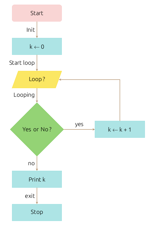
Flowtex Code
flowchart.offsetX("3");
  N('Start').belowGoto(
    P('k <- 0').belowGoto(
      loop = IO('Loop ?').belowGoto(
        D('Yes or No ?').offsetY(-1) // use offsetY with D
         .rightGoto(kp1 = P('k <- k + 1')).topLabel('yes')
         .belowGoto( // use offsetY for this node because is immediatly below of D
          P('Print k').offsetY(-1).belowGoto(
            P('Stop')
          ).leftLabel('exit')
        ).leftLabel('no')
      ).leftLabel('Looping')
    ).leftLabel('Start loop')
  ).leftLabel('Init');
  kp1.goto(loop).brokenArrow();
LaTeX code using TIKZ
\begin{center}
  \begin{tikzpicture}[node distance=2cm]
    \node (node0) [startstop] {Start};
    \node (node1) [process, below of=node0] {k $\leftarrow$ 0};
    \node (node2) [io, below of=node1] {Loop ?};
    \node (node3) [decision, below of=node2, yshift=-1cm] {Yes or No ?};
    \node (node4) [process, right of=node3, xshift=3cm] {k $\leftarrow$ k + 1};
    \node (node5) [process, below of=node3, yshift=-1cm] {Print k};
    \node (node6) [process, below of=node5] {Stop};
    \draw [arrow] (node3) --node[anchor=south] {yes} (node4);
    \draw [arrow] (node3) --node[anchor=east] {no} (node5);
    \draw [arrow] (node5) --node[anchor=east] {exit} (node6);
    \draw [arrow] (node2) --node[anchor=east] {Looping} (node3);
    \draw [arrow] (node1) --node[anchor=east] {Start loop} (node2);
    \draw [arrow] (node0) --node[anchor=east] {Init} (node1);
    \draw [arrow] (node4) |- (node2);
  \end{tikzpicture}
\end{center}
Currently I use \input to insert the generated LaTeX code.
But, I would like create a LaTeX command like this:
\begin{flowtex}
Here, the Flowtex code.
\end{flowtex}
Would you know how to do?


Best Answer
An alternative to the @A.Ellet answer (both consider the first version of your question):
From comparison of both solution you can observe the following main differences:
basequotespackage by which syntax for writing edges labels significantly shorter needed code.The compilation of above MWE (Minimal Working Example) produce similar picture as is shown in @A.Ellett answer with important differences: the feedback edge is drawn more correct (according to my opinion).